Chapter eight
SPECIAL MILITARY RADARS
8.1. TYPE 424N/424NB2
8.2. TYPE 424CCA
8.3. TYPE 424W
8.4. COASTAL ARTILLERY RADAR
8.5. CDR 431
8.6. DAGGER/RAPIER
8.7. AWS-6 GUARDSMAN
8.1. TYPE 424N/424NB2
A version of the 424, designed for the Royal Navy, was designated 424N. Its aim was to provide a fast landing rate for aircraft. It had an increased antenna turning rate (40rpm) and a higher power transmitter at 40kW. Although it never went into service it was the basis, in 1954, for the 424NB2, which detected the impact of practice bombs aimed at targets in the sea, this equipment being used at many RAF Bombing Ranges. The 12-inch rotating coil displays were modified to have a delayed time-base to give an expanded view of the target area. The echoes from bomb impact ‘water splashes’ were plotted on the DECCAPLOT. Range and bearings were measured to derive the accuracy of the bombing action. Like the 424, the 424NB2, (and its marine ancestors) operated from a 1000Hz power supply allowing many components to be small in size.
8.2. TYPE 424 CCA (CARRIER CONTROLLED APPROACH RADAR)
The 424CCA was a special version of the 424. The main, and most important difference was that the antenna, transmitter housing and turning gear were mounted on a stable platform to allow accurate control of aircraft making a landing on an aircraft carrier deck. Only one of these systems was supplied and installed on the Dutch Navy Ship ‘Karel Doorman’.
8.3. TYPE 424W (MINE WATCHING RADAR)
The 424W, although carrying the same indicator (424) was in fact of a completely new design. It operated from a ‘normal’ 240V, 50Hz mains supply. It had a new 14-foot double curvature cosec2 pattern antenna and a new 70kW X-band transmitter. It was supplied complete with an operations cabin and master PPI along with several ‘B’ scan photographic displays. The ‘B’ scan presentation was similar to an ‘A’ scan but with azimuth bearing on the X axis and range on the Y axis. Each display was set to show a sector, which was photographed by a cine camera modified for single shot operation, with the developed films then being used in mine clearance operations. A number of these equipments were sold to Sweden.
The principle characteristics of the 424W were:
- Frequency X- Band
- Receiver Noise Factor 12dB
- Aerial Gain 39.5dB
- Pulse Length 0.3S
- Rotation Rate 40 rpm
- Peak Power 70kW
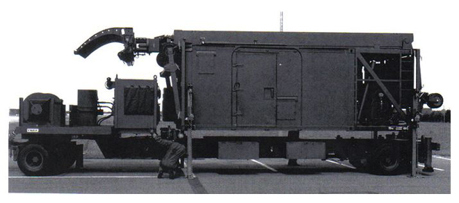
8.4. COASTAL ARTILLERY RADARS (CAR)
The Coastal Artillery Radar was a derivative of the 424W. It used a special slatted version of the 14foot double curvature antenna of the 424 design, this to reduce windage effect. It was supplied with an operations cabin, a master PPI and several operator-controlled ‘B’ scan displays and would detect the fall of shot from coastal guns, trajectory correction then being given to the guns. The only significant difference between the characteristics of the CAR and the 424W was that the antenna described a pencil beam with a gain of 42dB.
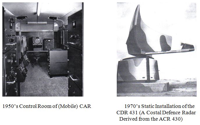
8.5. CDR 431
As the 424 gave rise to variant specialist equipments in the 1950/60’s, so did the ACR430 in the 1970’s.
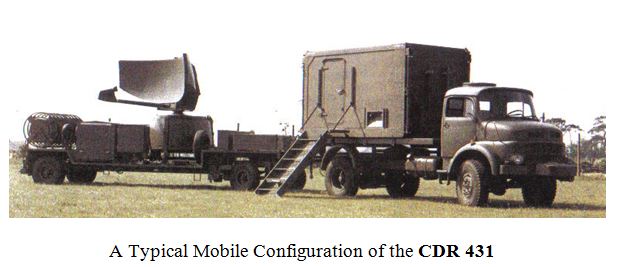
The principal change was to a fully mobile configuration of Transmitter/Antenna trailer and an operators cabin. The other main change was that the antenna had a main beam feed.
8.6. DAGGER/RAPIER
Along with the success of the VTOL Harrier in the Falklands war was that of the RAPIER Missile. Decca/Plessey Radar had from the outset been involved in the design, development and manufacture of the radar central to the RAPIER weapon system.
The equipment comprised a towed trailer containing a 2D Pulsed-Doppler surveillance radar mounted between a pair of missile launching rails. Design work on the radar began at Decca (Davis Road No.1) in 1961 – then a secret project named KEVIN. The only direct element of responsibility for the Cowes IOW based team, at that time, was that of design and manufacture of the metal sprayed/GRP backed antenna (a miniature AR1, cosec2 dish), also a number of waveguide sections manufactured from the same sprayed metal/GRP process.
Operating in S-band the small aperture gave a wide beam but the radars azimuth accuracy was adequate for laying-on the optical tracker during engagement. The Cowes based engineering team later developed the IFF antenna – a printed dipole array held in rigid foam. This version of RAPIER entered service in the mid 1970’s as ‘FIELD STANDARD A’ and was later updated to FS ‘B’ with a new signal processor and planar array antenna. 1980 saw the Decca/Plessey Cowes based team awarded a development and manufacturing contract for a radically new version of RAPIER, designated Field Standard ‘C’. The radar Company would be working with British Aerospace, (who had responsibility for missiles and all the related trailers) and with the MOD (RAF) acting as the projects technical authority - code name - DAGGER.
The Dagger product was designed to engage faster and lower flying aircraft, it would be helicopter transportable and proofed against ECM. Dagger would be a Pulsed/Doppler radar with 3D coverage operating in a much higher microwave frequency band than FS ‘A’ and ‘B’ and with much finer range resolution (some 3,000+ resolution cells). It employed RF and PRF agility with software based signal processing and track extraction.
Field standard ‘C’s configuration used a second trailer (always of BAE Systems design) to carry the missile launching system, complete with an electro-optic (Passive IR) tracker. A Marconi DN181 tracker (Blindfire) also formed part of the system.
Dagger satisfied all NATO design and supply demands. Field standard ‘C’ incorporated a variety of features, which were novel at the time of its design.
The planar array antenna comprised horizontal corporate feeds generating the azimuth beam, each fed from a waveguide and Rotman-derived lens, providing a stack of overlapping elevation beams with each elevation beam having its own receiver. The antenna was computer designed and NC machined directly from the digital data. Housed in a hemi-spherical blast-proof radome, the antenna, at 60rpm was rotated by a direct drive motor eliminating gearbox noise and vibration. New high voltage insulation methods were used to compact the transmitter into 0.25 cubic metres. Signal processing exploited a variety of clutter rejection and anti-jamming techniques. 3D plot extraction incorporated facilities for helicopter designation.
Unlike its predecessor, Dagger had no setting-up or other controls to adjust when in service or under maintenance. Dagger was designed to render target engagement automatically and swiftly, this within a few seconds from first detection to missile launch.

8.7. AWS – 6 (GUARDSMAN)
The major elements of the AWS-6 Radar were containerised and configured to be an integral part of a ‘Tactical Land Based Defence Weapon System’ taken to the market as ‘GUARDSMAN’ (for further details of the product turn to Chapter 10.7 and 10.8)